|
http://www.spinellis.gr/pubs/jrnl/2003-IEEESW-umlgraph/html/article.html This is an HTML rendering of a working paper draft that led to a publication. The publication should always be cited in preference to this draft using the following reference:
|
Diomidis Spinellis
Colleagues in my research group as well in collaborating institutions typically model software designs using graphical tools like Rational Rose, Together, and Visio. I often witness them toiling to adjust a graph's appearance with the mouse or laboriously visiting each class to change the type of a single field. This need not be so. I propose that design models should be composed textually, and graphs should be automatically generated. You may find it perverse to employ two different representations (textual and graphical) for the same underlying model. To substantiate my view I will therefore outline the advantages of graphical models, describe the benefits gained from directly manipulating a textual representation, illustrating my point by a prototype implementation.
There is no rule specifying that models should appear in a graphical form. A model is a simplification of reality, so a model for a software artifact could really be an outline of that artifact; think of a class definition without code in the method bodies. However, we usually prefer to examine many of our models in a graphical representation: UML employs nine different diagrams for visualizing different perspectives of a system.
Using a diagram to represent a model has a number of advantages. When we examine the graphical representation of a model we utilize our visual cognitive apparatus which has some millions of years of evolutionary advantage over our text-reading abilities. The two-dimensional representation of a diagram is a lot more expressive than text, which is typically scanned from the left to the right and the top to the bottom. Diagrams can be viewed following different directions to gain distinct insights, while the use of a larger symbol set makes them more expressive. In addition, one can obtain different levels of detail from the same diagram: a bird's eye view will easily convey a system's structure, while examining a class in detail can reveal its collaborators. Finally, a diagram can allow us to identify patterns; again two-dimensional pattern-matching is an activity we humans are particularly good at.
class Asset {}
class InterestBearingItem {}
class InsurableItem {}
/**
 * @extends InsurableItem
 * @extends InterestBearingItem
 */
class BankAccount extends Asset {}
/** @extends InsurableItem */
class RealEstate extends Asset {}
class Security extends Asset {}
class Stock extends Security {}
class Bond extends Security {}
class CheckingAccount extends BankAccount {}
class SavingsAccount extends BankAccount {}
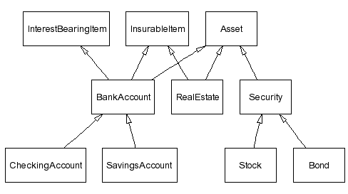
can be used to automatically create the diagram that appears below:

You can read more about the tools I use to generate such diagrams at http://www.spinellis.gr/sw/umlgraph.
Creating models in a declarative, textual notation offers a number of advantages. First of all, the model composition mechanism matches well both a programmer's high-level skills, the textual abstract formalization of concrete concepts, and the associated low-level skills, the manipulation of text using an editor and other text-based tools. The declarative notation, by being closer to the program's representation (the notation I experimented with is based on the Java syntax and semantics), forces the designer to distinguish between the model and the respective implementation, between the essential system characteristics and the trivial adornments. It is more difficult for designers to get away, as they often do now, with drawing for a model a nice picture of the implementation they have in mind. The declarative representation is also highly malleable, the existing visual structure does not hinder drastic changes, nor is effort wasted on the tidy arrangement of graph nodes a psychological barrier against massive design refactoring. Declarative models are also highly automatable: they can be easily generated from even higher-level descriptions by trivial scripts and tools operating on design process inputs such as database schemas, existing code, or structured requirements documents [2]. Text macro processors can be used for configuration management, while revision control and team integration activities can utilize the same proven tools and processes that are currently used for managing source code. Thus with a tool like RCS one can keep track of design revisions, create and merge branches, and monitor model changes, while a system like CVS can allow work to be split into teams. Finally, the declarative approach can readily utilize existing text processing tools for tasks that a drawing editor system may not provide. Consider how your favorite model editor handles the following tasks and how you could handle them using a simple Perl script or a text-processing pipeline applied to the declarative model specification: identify all classes containing a given field (as a prelude to an aspect-oriented cross-cut); count the total number of private fields in a given design; order methods appearing in multiple classes by their degree of commonality; identify differences between two designs.
The declarative specification of software models is clearly not a panacea. Our current UML diagram design prototype stresses dot, the underlying graph layout generator, resulting for example in association multiplicity and visibility adornments overlapping with the respective edges. Furthermore, learning the declarative notation may be more difficult than experimenting with the toolbars of a GUI-based diagram editor competing for the designer's attention. However, since the maturity of a profession is also judged by tools used by its practitioners, I believe that building and adopting a sharp declarative modeling toolset will enrich and advance the software engineering discipline.